Hello there,
Im currently building a printer with custom kinematics. The hardware is almost done, however, Im currently banging my head against a wall, trying to make it move as i should.
The kinematics go as such, the Z and Y axis are simple enough, resembling a Cartesian style of printer, the only twist being that there is only 1 Z motor, and 2 Y motors that work intend um.
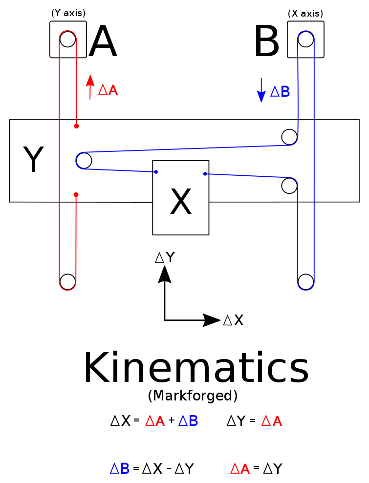
It is with the X axis, that stuff gets somewhat interesting, since the Y and X are connected via the carriage and thus need to move to account for each other.
It is somewhat similar to markforges mechanism, except with dual Y motors, heres a screenshot;
![Image: https://cdn.hackaday.io/images/2988881485085759090.png]()
I would really appreciate any and all help, I can get in my endeavor, especially given that this will eventually be an open source design, and I am terrible at coding.
pls halp
Im currently building a printer with custom kinematics. The hardware is almost done, however, Im currently banging my head against a wall, trying to make it move as i should.
The kinematics go as such, the Z and Y axis are simple enough, resembling a Cartesian style of printer, the only twist being that there is only 1 Z motor, and 2 Y motors that work intend um.
It is with the X axis, that stuff gets somewhat interesting, since the Y and X are connected via the carriage and thus need to move to account for each other.
It is somewhat similar to markforges mechanism, except with dual Y motors, heres a screenshot;

I would really appreciate any and all help, I can get in my endeavor, especially given that this will eventually be an open source design, and I am terrible at coding.
pls halp